Another spark gap transmitter (a little more powerful) can be found on SM0VPO's page. If you're interested, I also found an interesting article about spark gap transmitters, covering both history and the technical details.
When experimenting with resonant transformer circuits and a Cockroft ladder, I realized the burst of sparks created probably emitted quite a bit of electromagnetic radiation of various frequencies, from longwave to ultraviolet light. I had in fact reinvented a version of the infamous spark gap transmitter, banned on the amateur bands since 1924. Can there be any better way to celebrate this 80th anniversary than actually building one?
Spark gap transmitters have a number of advantages, when compared to "modern" CW transmitters.
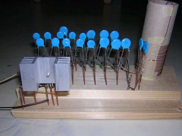
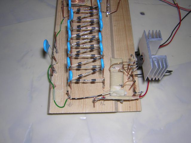
How does the one I built work? First of all I use a Power MOSFET transistor to oscillate a transformer, hand-wound on a ferrite rod used in an old AM radio antenna. The gate of the MOSFET is biased by one 1k and one 2.2k resistor, which gives a voltage of about 3V from an input voltage of around 10V - just what we want, since that is close to the MOSFET's turn-on voltage. Note: after replacing the old MOSFET with a BUZ71A, I had to change the 2.2k resistor to a 1k one.
So when the key is presseed, the MOSFET starts conducting, which induces a negative voltage to the gate, so the MOSFET turns off. This in turn makes the voltage on the gate go up again, and we have completed one cycle. This is of course not my own idea, I just used a flyback driver circuit I found on the web, replaced the BJT with a MOSFET (I tried, and fried, a large pile of BJTs before discovering MOSFETs are way better for this circuit). With a pair of back-to-back zeners from the gate to ground, you can avoid some of the nasty high-voltage spikes that cost a good MOSFET its life.
The secondary side of this oscillating transformer consists of a number of (well-insulated, since I have had enough of arcovers inside the transformer) turns of enameled 0.15mm copper wire. The output is connected to an 8-stage Cockroft ladder, using 3kV 4.7nF ceramic capacitors and pairs of 1N4007 diodes (to get a maximum back voltage of about 2kV). This is where I started experimenting.
The first thing you'll need is a spark gap. Making it a bit below 1mm works fine for me, I get enough sparks per second to produce a steady "tone". Now you connect some sort of resonant circuit to the positive end of this spark gap, as its voltage will drop very rapidly when the spark discharges the capacitors. The simpliest form of a resonant circuit is a piece of wire - an antenna. I've also experimented with a simple LC circuit, but I can't really measure the output power/signal bandwidth so I don't know if that made things worse or better. Using a few tuned stages ensures a narrowed bandwidth, but of course makes the circuit more complex. For now a simple antenna connected directly to the spark gap will have to do.
I connected a wire, about 6 meters long, to the spark gap, and threw together a simple AM receiver connected to a dipole antenna (also 6 meters), and went outside with my slave (sister). The signal got too weak about 30 meters away. With a better receiver I guess a few hundred meters is possible using this transmitter, but (fortunately) it's not suited for DXing.